

Differential pressure transmitter applications are remarkably broad: from boiler drum level and orifice-plate flow measurement to closed-tank level, filter monitoring and cleanroom pressure control. This article summarises the 10 most common applications according to European practice and standards (EN, ISO, EU GMP, ATEX), with installation tips for accurate, long-lasting measurement.
What is a DP transmitter? Measuring principle and uses
A differential pressure transmitter measures the difference between its H (high) and L (low) ports: ΔP = PH – PL. Pressure acts on a capacitive or piezoresistive silicon sensor; the signal is digitised (18-bit A/D), linearised and temperature-compensated by a microprocessor and output as 4–20 mA/HART – linear or square-root for flow. From a single ΔP value you can derive level, flow, density or filter clogging.
10 differential pressure transmitter applications to EU standards
1. Boiler drum level measurement with DP transmitters
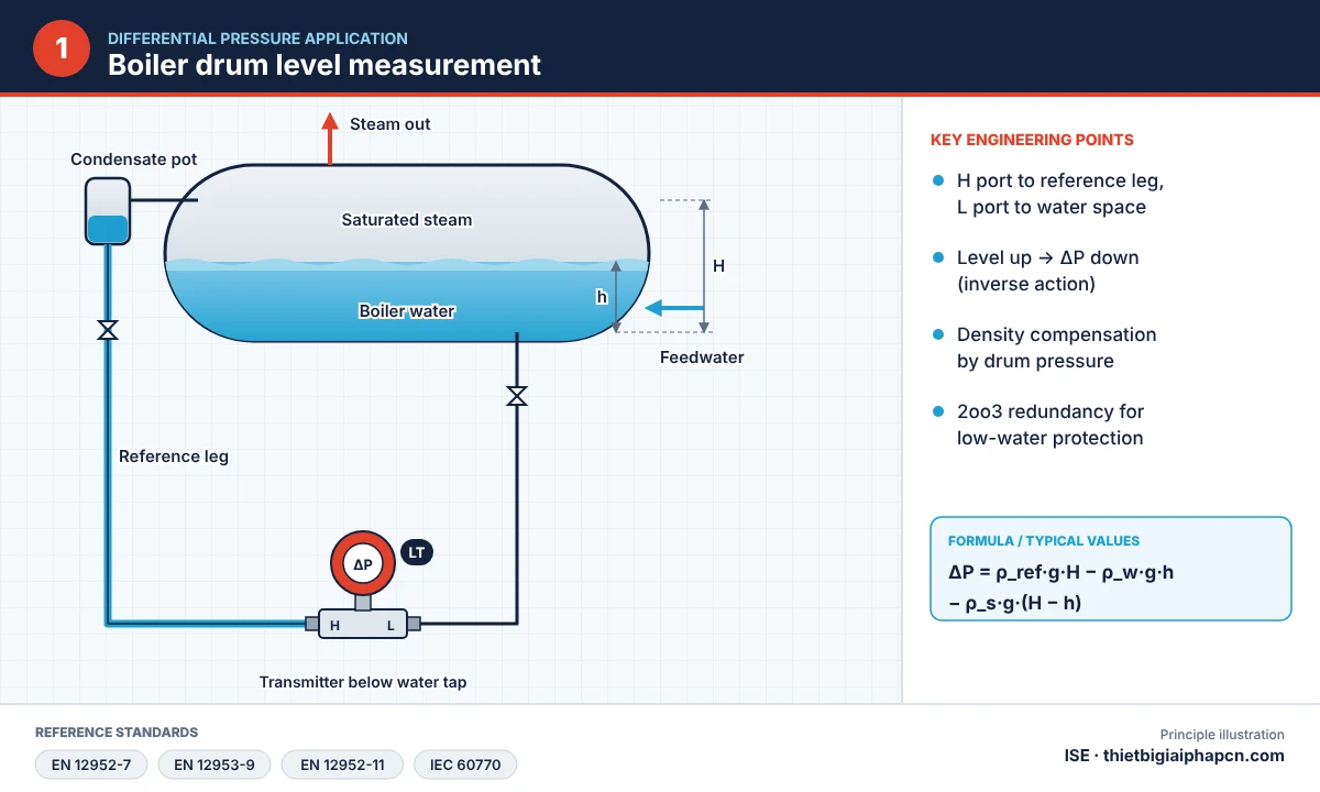

Boilers run at high temperature and pressure, so DP is the standard level method: the H port connects to the water side, the L port to the steam space via a condensing chamber – reference leg filled with water (wet leg). ΔP is inversely proportional to level, requiring negative range suppression and water/steam density compensation with pressure. Level indication and limiting devices for boilers are covered by EN 12952 (water-tube) and EN 12953 (shell boilers). Complete solution: boiler drum level measurement system.
2. Steam, gas and liquid flow through orifice plates
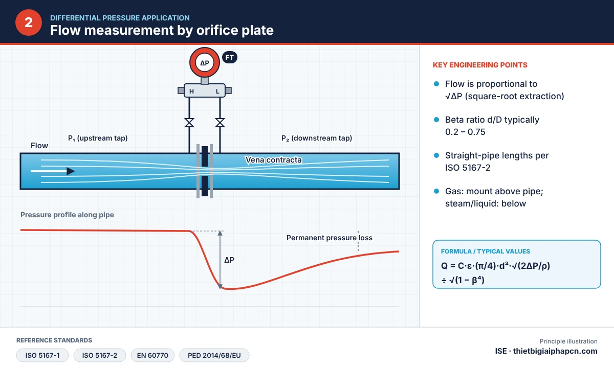

Orifice plates, venturi tubes and nozzles create a ΔP proportional to flow squared (Q ∝ √ΔP). A DP transmitter with square-root output gives a signal linear with flow. Primary elements are designed and installed to ISO 5167 (ISO 5167-2 – orifice plates). Adding pressure and temperature measurement gives saturated/superheated steam mass flow. Much lower cost than a vortex flow meter on large pipes.
| Medium | Tap position | Transmitter position |
|---|---|---|
| Liquid | Taps on the side of the pipe | Beside or below the taps so gas bubbles vent back to the pipe |
| Gas | Taps on top or side of the pipe | Beside or above the pipe so condensate drains back |
| Steam | Taps on the side of the pipe | Below the taps; fill impulse lines with water before start-up |
3. Continuous level in open and pressurised tanks
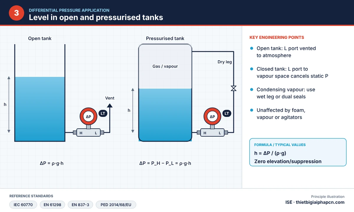
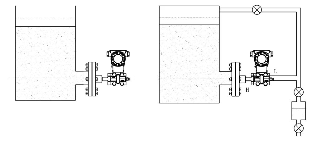
ΔP = ρ·g·h – it depends only on liquid height and density, not tank shape. Open tank: H port at the bottom, L port vented. Closed tank: L port connected to the vapour space to cancel static pressure P0; use a dry leg if vapour does not condense, a wet leg if it can. For corrosive, viscous or crystallising media use flanged or capillary remote-seal DP transmitters.

4. Density and liquid interface
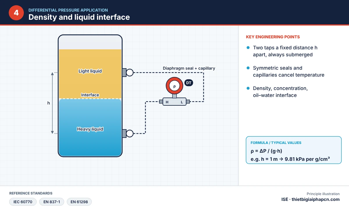
Two taps a fixed distance h apart: ΔP = ρ·g·h, so ΔP is directly proportional to density. Used for solution concentration (milk, syrup, acids) and oil–water interface in separators.
5. Baghouse dust collector monitoring
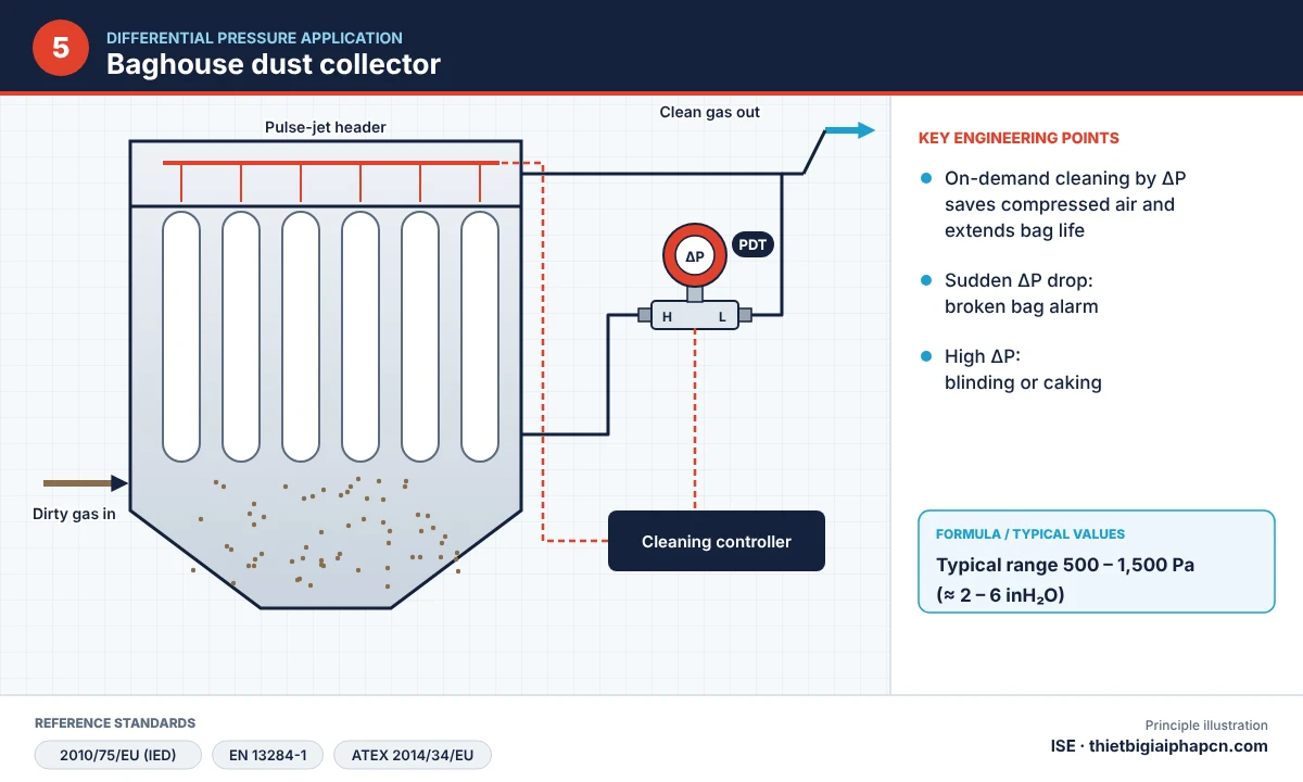

Measuring ΔP across a bag filter enables on-demand pulse-jet cleaning and alarms for torn or blinded bags. ΔP-based cleaning extends bag life, saves compressed air and keeps outlet dust within emission limits.
6. HVAC and AHU air filter monitoring
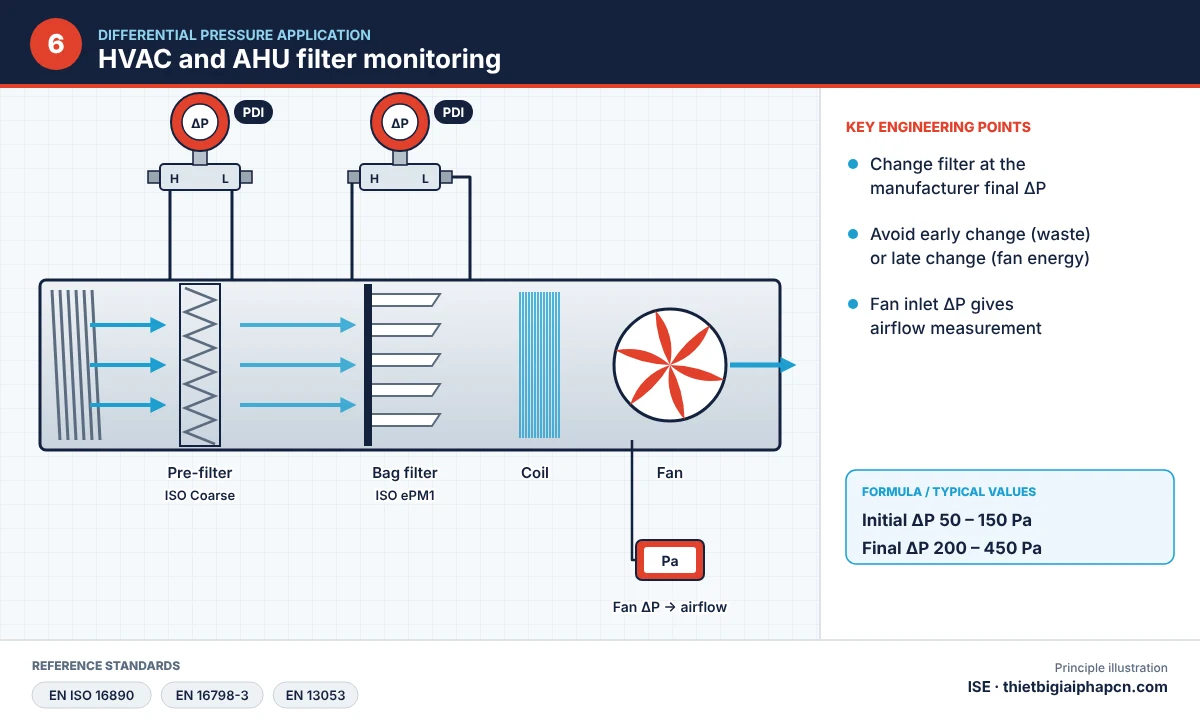
ΔP across a filter rises as dust loads. When the manufacturer’s final pressure drop is reached, replace the filter – avoiding premature changes or excessive fan energy. Coarse/fine filters are classified to ISO 16890, HEPA/ULPA to EN 1822. Ranges from a few hundred Pa to a few kPa.
7. Cleanroom pressure in pharmaceutical plants and hospitals
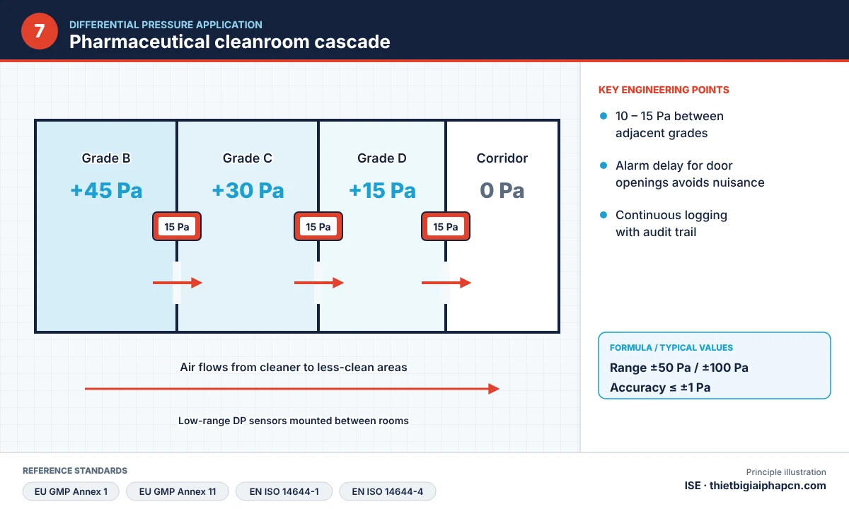
Cleanrooms must stay positive (or negative for isolation rooms) relative to adjacent areas to prevent cross-contamination. EU GMP Annex 1 recommends at least 10 Pa between adjacent rooms of different grades; cleanrooms are classified to ISO 14644. Very-low-range DP transmitters (0–100 Pa or 0–1.5 kPa) with logging and alarms are needed – see the CST-MDP low differential pressure transmitter.
8. Liquid filters, strainers and pumps
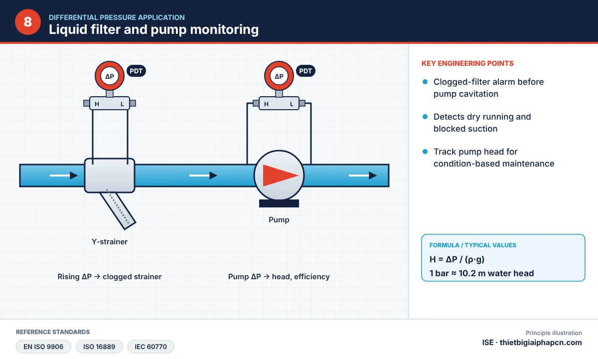
ΔP across feedwater filters, fuel oil filters and Y-strainers indicates when cleaning is needed; suction–discharge ΔP monitors pump performance and detects cavitation.
9. Furnace draft and combustion chamber pressure
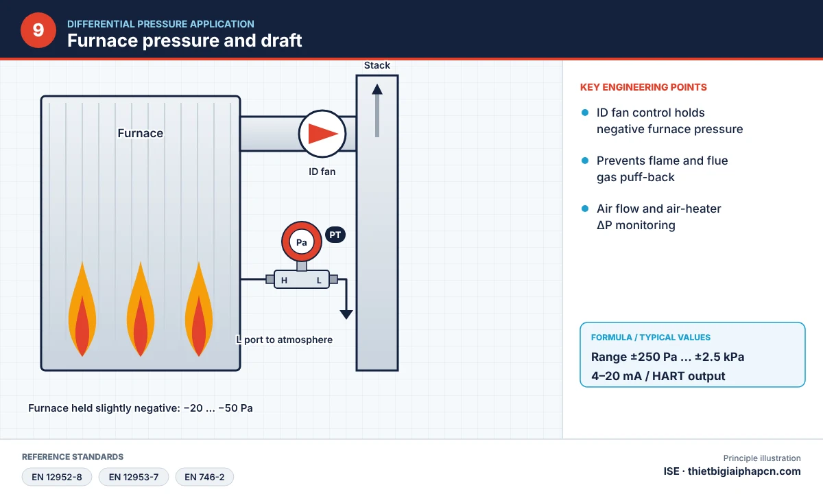
Boilers, kilns and dryers need stable slightly negative furnace pressure. A low-range DP transmitter measures furnace pressure against atmosphere to control the ID fan VFD – combined with boiler oxygen trim control for fuel savings.
10. Hazardous areas (ATEX)
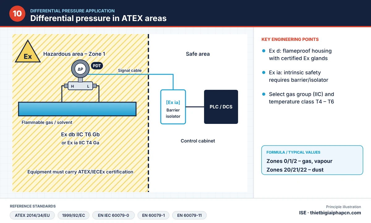
Chemical, oil & gas, paint and wood/powder plants use intrinsically safe Ex ia or flameproof Ex d DP transmitters certified to the ATEX Directive 2014/34/EU and the IEC/EN 60079 series. Actual safety parameters are always those on the nameplate and certificate of each unit.
DP transmitter specifications for industrial applications
| Parameter | Value |
|---|---|
| Sensor | Capacitive or piezoresistive silicon, 18-bit A/D |
| Range | From 0–0.1…1.5 kPa to 0–20.68 MPa (re-rangeable on site) |
| Max. static pressure | 14 MPa / 25 MPa / 32 MPa (optional) |
| Output | 4–20 mA + HART®, linear or square-root |
| Diaphragm | 316L stainless, Hastelloy C |
| Fill fluid | Silicone oil, fluorinated oil (for oxygen, chlorine) |
| Display | LCD: pressure, %, loop current, sensor temperature; push-button zero/span |
| Explosion protection | Ex ia IIC T4–T6 / Ex d IIC T4–T6 (optional) |
| Mounting | Standard chamber type, direct-mount flange, capillary remote seal |
Product details: CST305X-DPT differential pressure transmitter and CST-MDP low DP transmitter.
Impulse line installation for DP transmitter applications
- Keep impulse lines as short as possible; keep H and L legs at the same temperature.
- Liquid/steam: slope lines upward to the process tap at least 1:12; gas: slope downward to the tap at least 1:12.
- Avoid high points in liquid lines (trapped gas) and low points in gas lines (trapped liquid).
- Use a 3-valve manifold for safe isolation, equalising and zeroing.
- Do not megger the signal loop with high voltage – test at max. 100 VDC.
- Zero after installation in the final position; earth the housing correctly.
How to choose a DP transmitter for each application
Each differential pressure transmitter application needs a different range, materials and mounting. Determine:
- Application: level, flow, filter or cleanroom → range and linear/square-root output.
- ΔP range and static pressure of the line or vessel.
- Medium and temperature: diaphragm, fill fluid, remote seals if needed.
- Area: safe or ATEX (Ex ia/Ex d); weather protection outdoors.
- Signal: 4–20 mA, HART to PLC/DCS.
FAQ on differential pressure transmitter applications
How does a DP transmitter differ from a pressure transmitter?
A pressure transmitter measures against atmosphere or vacuum; a DP transmitter measures the difference between any two points, even when both are at very high static pressure.
Why is square-root output used for flow?
Because ΔP across an orifice is proportional to flow squared. In-transmitter square-root extraction makes the 4–20 mA signal linear with flow, so the PLC needs no extra calculation.
How do I measure level in a closed tank with condensing vapour?
Use a wet leg filled with liquid on the L side with negative range suppression, or a DP transmitter with dual capillary remote seals.
Related products
- HART differential pressure transmitter
- Low differential pressure transmitter
- 3-valve manifold
- Boiler drum level measurement system
- Vortex flow meter
Where to buy differential pressure transmitters?
EQUIPMENT INDUSTRIAL SOLUTION CO., LTD (ISE) – Ho Chi Minh City, Vietnam – supplies genuine differential pressure transmitters with technical consulting, fast quotation and on-site commissioning support across Vietnam and Southeast Asia.
Contact us: Sales +84 909 617 185 – Technical +84 979 117 185 – Email: [email protected]


