
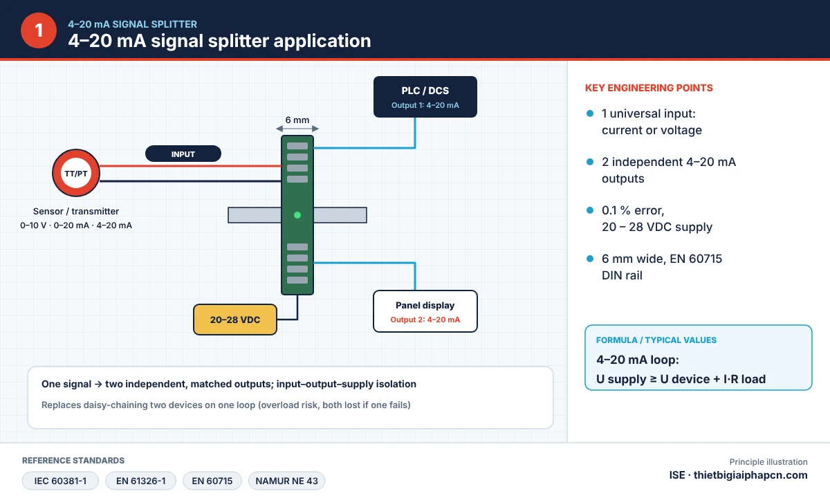
This slim 6 mm 4-20 mA signal splitter takes one analogue signal and delivers two independent 4–20 mA outputs, while isolating against noise and acting as a 0-10 V to 4-20 mA converter. One sensor signal can feed both a PLC and a local display with matched channels, without daisy-chaining two devices on one current loop.

How the 4-20 mA signal splitter works
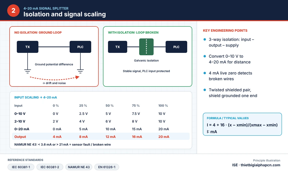
The input (current or voltage) is measured, galvanically isolated and regenerated as two separate 4–20 mA current sources. With 3-way input–output–supply isolation, ground potential differences between sensor, PLC and display cannot drive leakage currents, so the signal does not drift; if one receiver fails or opens, the other output keeps working.
Specifications
| Parameter | Value |
|---|---|
| Input (1 channel) | 0–20 mA, 4–20 mA, 0–5 V, 1–5 V, 0–10 V, 2–10 V |
| Outputs (2 channels) | 4–20 mA, independent |
| Supply | 20 – 28 VDC |
| Error | 0.1 % |
| Isolation | Input – output – supply, noise rejection |
| Size | 6 mm wide, 35 mm DIN rail (EN 60715) |

0-10 V to 4-20 mA conversion
Voltage signals suffer from losses and noise over distance. The splitter scales the input linearly to current: I = 4 + 16 · (x − xmin)/(xmax − xmin) mA – for example 5 V on a 0–10 V range gives 12 mA. The 4 mA live zero reveals broken wires; per NAMUR NE 43, below 3.6 mA or above 21 mA indicates a fault.
Applications

- Display and control in two places: PLC and panel meter, or local panel and control room.
- Splitting pressure, level and flow signals for boiler and energy monitoring.
- Converting 0–10 V outputs of inverters and controllers to 4–20 mA for long runs.
- Breaking ground loops when signals drift or are noisy.
For a splitter with LED indication and detailed order codes, see the CST ISIE 4-20 mA signal isolator. More devices in signal converters.
Installation notes
- Use shielded twisted pair, shield grounded at one end (panel side).
- Keep each output’s total load within the manufacturer’s limit.
- Route signal cables away from power and inverter cables.
- Check 4, 12 and 20 mA with a calibrator after installation.
Reference standards
| Standard | Scope |
|---|---|
| IEC 60381-1 | Analogue current signals for process control |
| IEC 60381-2 | Analogue voltage signals |
| NAMUR NE 43 | Failure signal levels |
| EN 61326-1, 2014/30/EU | Electromagnetic compatibility |
| EN 61010-1, 2014/35/EU | Electrical safety |
| EN 60715 | 35 mm DIN rail |
FAQ
Can a PLC and a meter share one 4–20 mA loop in series?
Yes if the supply covers the total load, but if one device opens the whole loop is lost and both share ground noise. A splitter gives two independent outputs and is safer.
Can the splitter replace a temperature transmitter?
No. Its input is a standard current or voltage signal; Pt100 or thermocouples need a temperature transmitter.
Product video:
Contact EQUIPMENT INDUSTRIAL SOLUTION CO., LTD (ISE) – Sales +84 909 617 185 – Technical +84 979 117 185 – [email protected].


