
Boiler fan control with variable speed drives (VFDs) is the most effective way to cut the power drawn by forced-draft (FD), induced-draft (ID) and fluidising fans while keeping furnace pressure stable and combustion efficient. ISE designs, supplies and programs fan control systems for steam boilers and thermal oil heaters following European practice (EN 12953-7, EN 12952-8, Regulation (EU) 2019/1781).
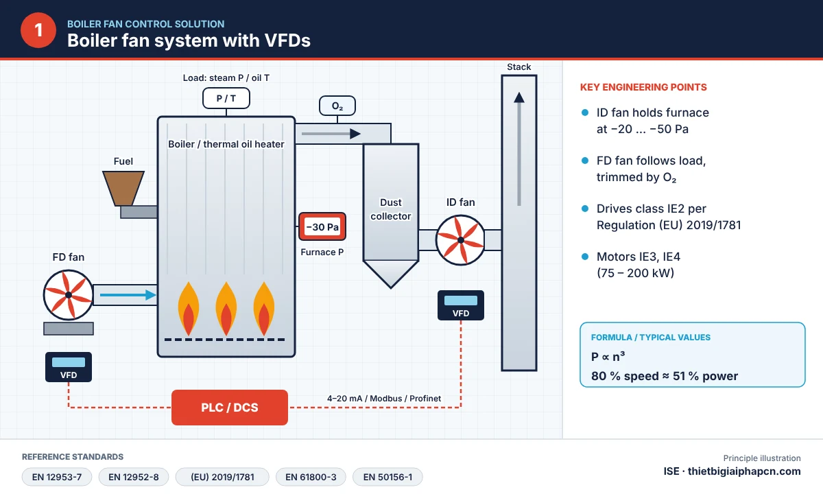
Why boiler fan control matters
Fans are the largest electrical load on a boiler. Boilers rarely run at full load, so airflow must follow steam pressure or thermal oil temperature. If fans run at full speed and air is throttled by dampers, the surplus energy is lost as pressure drop, motors and bearings run fully loaded, furnace pressure fluctuates and high excess air lowers combustion efficiency.
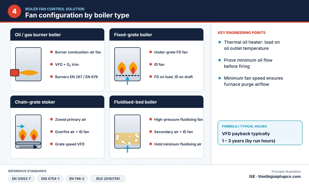
Boiler types and fan configuration
| Boiler type | Fans | Main control point |
|---|---|---|
| Oil (DO, HFO) or gas (LPG, CNG, biogas) burner boilers | Burner combustion-air fan | VFD + O₂ trim; burners to EN 267 / EN 676 |
| Fixed-grate boilers | Under-grate FD fan, ID fan | FD on load, ID on furnace pressure |
| Chain-grate stokers | Zoned primary air, overfire air, ID fan | Plus grate speed VFD on load |
| Fluidised-bed boilers | High-pressure fluidising fan, secondary air, ID fan | Hold minimum fluidising airflow |
| Thermal oil heaters | As above | Load on oil outlet temperature; prove oil flow before firing |
Boiler fan control: damper versus VFD
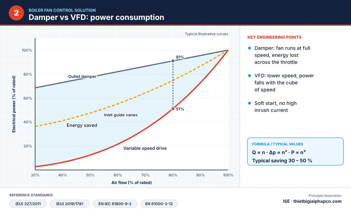
Damper control
The fan always runs at full speed; airflow and head are adjusted by opening or closing dampers.
- Pros: low initial cost.
- Cons: high energy loss, high inrush current, faster wear of motors, bearings and dampers; dampers stick and control is slow and imprecise.
Variable speed drive control
The fan runs at the speed the load needs, set by a 4–20 mA or fieldbus signal from the PLC. By the fan affinity laws, flow follows speed, pressure follows speed squared and power follows speed cubed – 80 % speed needs only about 51 % power.
- Pros: typically 30–50 % energy saving on variable loads; soft start; longer motor and equipment life; faster, more accurate control; less maintenance.
- Cons: higher investment; harmonics and EMC must be handled correctly.
Field example: at the Valorsul waste-to-energy plant in Portugal, replacing damper control with drives on three ID fans and three secondary air fans cut consumption by about 9 MWh/day, saving about €240,000 a year with a payback of about 3 years (ABB case note). For small and medium industrial boilers, payback is typically 1–3 years depending on fan power and running hours.
Fan and combustion control loops
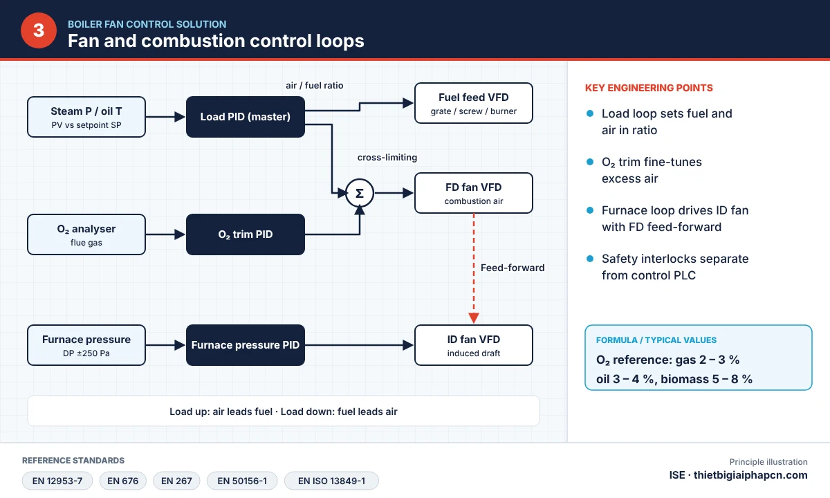
- Load loop (master): compares steam pressure or oil outlet temperature with setpoint and drives the fuel-feed and FD fan VFDs in air/fuel ratio with cross-limiting (on load increase air leads; on decrease fuel leads).
- O₂ trim: an oxygen analyzer in the flue gas fine-tunes excess air – see boiler oxygen trim control.
- Furnace pressure loop: a differential pressure sensor (±250 Pa) measures furnace pressure and a PID drives the ID fan VFD to hold −20 … −50 Pa, with feed-forward from the FD fan.
- Safety interlocks: pre-purge, minimum fan speed, trip on loss of air or high furnace pressure – independent of the control PLC per EN 50156-1 and EN 12953-7.
EU standards for boiler fan control
| Standard | Scope |
|---|---|
| EN 12953-7 / EN 12952-8 | Firing system requirements for shell / water-tube boilers, air–fuel interlocks |
| EN 676 / EN 267 | Forced-draught burners for gaseous / liquid fuels, air ratio control |
| EN 50156-1 | Electrical equipment of furnaces, safety systems |
| Regulation (EU) 2019/1781 | Drives minimum IE2; motors IE3 (0.75–1000 kW), IE4 (75–200 kW) from July 2023 |
| Regulation (EU) 327/2011 | Minimum efficiency of fans 125 W – 500 kW |
| EN 61800-3 / EN 61000-3-12 | Drive EMC and harmonics |
| DIN 4754-1 | Safety of thermal oil installations |
Benefits of ISE boiler fan control
- 30–50 % lower fan energy on variable loads.
- Stable furnace pressure, no puff-back; optimum combustion with O₂ trim and lower fuel use.
- Soft start, fewer mechanical failures, lower maintenance.
- Operating data to SCADA, supporting continuous emission monitoring and energy reporting.
Project steps
- Survey fans, motors, load profile and running hours; estimate savings.
- Select IE2 drives, line reactors/harmonic filters and IE3/IE4 motors where replacement is needed.
- Install differential pressure, O₂ and load (pressure/temperature) sensors.
- Program the PLC: load loop, O₂ trim, furnace pressure, safety interlocks; HMI/SCADA integration.
- Commissioning, tuning and operator training.
FAQ
Should the dampers be kept after installing VFDs?
Yes, kept fully open for bypass operation or cold start; flow control moves to the drives.
Does the ID fan need a VFD if the FD fan has one?
Yes. If FD airflow drops while the ID fan runs at full speed, the furnace becomes too negative, increasing air ingress and heat loss. Controlling both keeps furnace pressure stable.
Related
- 10 differential pressure transmitter applications
- Flue gas analyzer CO, NO, SO₂
- Boiler TDS control solution
Contact ISE about boiler fan control
EQUIPMENT INDUSTRIAL SOLUTION CO., LTD (ISE) – Ho Chi Minh City, Vietnam.
Contact us: Sales +84 909 617 185 – Technical +84 979 117 185 – Email: [email protected]


